Noise Ring Deluxe Martian Space Party-Freak Out Version
The story of this deeply complicated descendant of the Goldberg Function Generator/Noise Ring family is damn near a Tolstoy novel in its scope!
It all starts in 2000 A.D. with the Goldberg Function Generator.
For the sake of the continuity, I strongly recommend you read the account in the link above.
So at this point we can summarize by saying that the Noise Ring was a deep collaboration between Grant Richter and myself.
I never conceived the Goldbergs as audio devices but Grant had the vision to see the considerable potential there.
Here’s how the Noise Ring as released by Grant at Wiard works:
(It will help to consult the Noise Ring block diagram below, at this point).
The Noise Ring uses analog noise at a basic source point in it’s algorithm, but never directly. This noise is never sampled by an sample/hold circuit, in fact there are no sample/hold circuits in the Noise Ring.
You may already know how a shift register works but for anyone who doesn’t, I’m going to use the analogy of a conveyer belt with room for 8 people….
In the Noise Ring, analog noise is only used to tickle the threshold of a comparator, the comparator flips on and off producing either ‘someone’ or ‘no one’, depending on the state of the comparator. This person/non-person stands on the doorstep of the conveyer belt, waiting for a signal. The signal comes from the clock. Like the comparator, the clock is also a 2-state device. We’ll call them ‘tick’ and ‘tock’. Remember that the clock in the Noise Ring is not steady. It varies with a CV. This is important. When the clock is in a ‘tock’ state , nothing happens. The conveyer belt doesn’t move and no one steps on. The Noise Ring’s output is static. But when the clock switches to “tick” the conveyer belt moves one step and if the comparator was tickled to it’s ‘someone’ state, someone steps aboard. If it was in ‘no one’ state, the conveyer moves one step with an empty place. On the next tick, whenever it arrives, the conveyer lurches forward and if anyone was in the last (8th) position they get dumped off.
Another thing happens at each tick, the DAC takes a snapshot of the pattern of occupied and unoccupied places on the conveyer, and based on that pattern it sends a voltage to the output, a different voltage for every different pattern, Thus as the two devices, comparator and clock, go on flickering , the conveyer gets loaded with different patterns that SHIFT on each tick. This irregular cycling of patterns is the heart of the Noise Ring’s method, and this is very close to the classic function of a digital shift register but with the important distinction that nothing is bound to a regular clock or a steady rate of change. That CAN happen but the design does not enforce it.
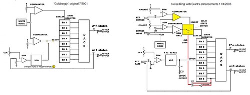
This conveyer-belt routine is the ‘Goldberg Function’ core that I conceived . One of the more brilliant twists on this concept that Grant conceived is depicted in the block diagram by the red line marked ‘old data’ feeding the “solid state switch’ . This is controlled by the ‘Change’ control. As the ‘Change’ control vector decreases, the chances INCREASE that the passenger who was just dumped off the end of the conveyer will get another turn and move right back to the front of the conveyer again and prevents any ‘new’ passengers (from the flickering comparator) from boarding. The effect of this is a ‘circular’ buffer wherein the pattern repeats ad infinitum until ‘new’ passengers are re-introduced by increasing the change control. At slow clock rates this results in cycling patterns. At audio clock rates the effect is a clearly discernible pitch. The wonderful thing about this is that the change control vector is continuous and thus, at audio frequencies, random audio (noise) will start to organize itself into a pitched tone. The ‘between states’ are sublime (to my perverse ear, anyway) and if you descend into chaos again , when you morph to pitch the next time there’s no guarantee that you’ll get the same wave as before.
This is the classic Noise Ring scheme.
In 2009 Grant and I began discussing potential expansions for this scheme based on the work of Claude Shannon. I built a Noise Ring on perfboard in which the 8 data lines could be easily tapped to facilitate experimentation. This perfboard prototype is in the final electronium version. As Grant and I discussed the the expansions, I tried them out in various prototypes and played the results for him over the phone.
Two expansion ideas emerged from these months of brainstorming:
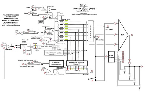
-Channel ‘X’ (XOR)
This was a permutation scheme created by 8-selectable combinations of XOR logic gates that rearranged the shift registers patterns in realtime. A 3-bit control scheme could thus dynamically change the patterns in addition to the classic Noise Ring inputs, adding a new dimension to the two Noise Ring DAC outputs.
-Channel ‘Z’ (in honor of the B52’s)
This enhancement added a new output DAC which used a pattern derived by selectively disabling bits in the the 8 bit data bus. This sounds simplistic but when the bits are disabled at audio rates, the output takes on a very harmonically rich FM-like character.
Using my perfboard Noise Ring platform I built a prototype that implemented both of these schemes and hopped on the Amtrak Hiawatha for Milwaukee in the fall of 2010. Grant and I tested and tweaked these schemes for about 5 days. The ‘Channel X’ scheme worked very reliably but the ‘Channel Z’ circuit had a tendency to build up excessive heat when it ran for more than about 20 minutes. We were both a bit discouraged because ‘Channel Z’ tended to yield the most dramatic sound. But my time for this junket was up. So I relutantly packed-up the prototype and returned home.
Grant had more pressing concerns in the management of Wiard to tend to. But I kept returning to the problem in the Channel Z scheme and it took ten years but I finally got a version that worked reliably.
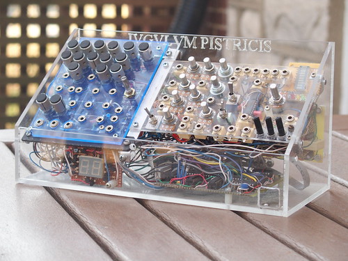
I added a module that provided an array of on-board control voltages and a few utility audio processors and mounted the result in (what else?) a clear acrylic box as you see it at the top.
Below is the final(?) panel layout.
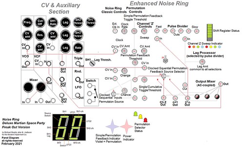
I agonized a bit over whether this device belonged on the Electronium page or the Modules Page. The Noise Ring, as Grant designed it, is unequivocally a module . Grant nicely optimized the design to play nice in any modular system as either a control-voltage source or an audio signal source. The instrument above could be used in similar fashion but I optimized the enhanced noise ring sections for use as AUDIO sources (ie I AC-coupled the outputs) and I added a whole array of on-board control voltage generators on the left panel so that the gizmo could sit on a table and do a gig all by itself. That attribute is why this instrument is corralled here with the electroniums.
A word about the names.
This circuit has had many names as it was volleyed back & forth between Grant & myself. It began as ‘The Goldberg Function Generator’ in 2000 , which begat the ‘Goldberg Jr.’ in 2001, which begat the ‘Noise Ring’ in 2002 and finally, as an electronium, it resides under the name “Noise Ring, Deluxe Martian Space Party – Freak Out Version” in the plastic box depicted.
But … You’ll notice that ‘Iugulum Pistricis’ is etched on the enclosure.
Well, that was kind of an accident. The perfboard that I built just happened to fit exactly on the floor of a box that had once housed an aborted project that I named ‘Iugulum Pistricis’.
Iugulum Pistricis is Latin. It means, The throat of the sea monster.
Why let such an evocative legend evict a device with a history as rich as the Noise Ring?
Comments are closed.