A handy 555 device
When the DIY bug bit me and I began to believe that I really could build analog circuits worth playing as instruments. One of my very first references was a tiny book from Radio Shack by the venerable sensei, Forrest Mims III . The title was “Engineer’s Mini-Notebook-555 timer IC circuits” . It was barely more than a pamphlet, but in a style true to this redoubtable author, it was direct, clear and APPROACHABLE. Using this little book , I was able to wire up useful, working circuits in a single evening. It is impossible to overstate how portentous this experience was in my life, and I hold Mr. Mims work in the highest regard as a result. If you want to get a good start on learning practical electronics. Anything by Forrest Mims is almost certain to help you.
So the 555 chip is sort of my first kiss, and very dear to me. It’s a very popular, ubiquitous, and handy chip that has been in use for decades. It has its flaws (and who among us doesn’t?) but It is very reliable and has myriad applications in analog synthesis.
This article is describes a circuit and how its design evolved. If you are so-inclined & possess the skills, you can build this circuit yourself.
A DIY article must disclaim a few things preemptively.
This article presents the design as a schematic diagram. This assumes the reader can read a schematic and has the tools and skills to build a circuit using the schematic as a blueprint. This article is not a tutorial in how to build electronic circuits accurately and safely. If you want to learn those skills I strongly recommend this book:
Handmade Electronic Music by Nicolas Collins
Alternately, there are hundreds of video tutorials on the internet that can guide a diligent novice to a level of proficiency sufficient to build the subject device.
With that disclaimer declared. Let’s jump right in.
Here is the schematic:
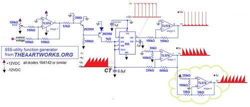
The experienced DIYers among you may not need anything more. But there are some interesting features of this design that I stole from some guys who are way smarter than me and you may find my comments on these ‘procurements’ illuminating .
OVERALL:
The main body of the schematic uses one 555 and 3 stages of one TL074 quad op-amp. Other quad op-amps with FET-input characteristics may work in substitution for the TL074, but I have only tested this design with the TL074.
The circuit yields:
– a very sharp, high-amplitude, positive-going trigger that is useful for triggering envelope-generators.
– a downgoing sawtooth waveform between 0v & 5v
The fourth stage of the TL074 can be utilized to yield an upgoing ‘ramp’ waveform. This option is shown in the green ‘cloud’ on the schematic.
The range of voltage control is from roughly +2V to +10v. Of course this range can be manipulated by the standard rules for a DC-coupled inverting op-amp mixer. (stage 1)
HOW IT WORKS:
In the following description of how this device works, and WHY it works that way, it’s important to note that the core 555 chip is a unipolar device. But NOTE in this case, It is operated between a high rail at ground (0v) and a low rail at -12v. This a bit unusual and I’ll explain the reason for this in the last section.
the trigger output
A Problem with a 555, wired as in the schematic above , is that its main output at pin 3 stays high, near the voltage at the power supply pin 8 and at each ‘tick’ it zips all the way down to the low rail at pin 1, and right back up VERY fast. This excursion from ‘rail-to-rail’ is powerful electrically, but quick; in the vicinity of less than a millisecond(!).
There are many ways to manipulate the timing and amplitude of this output. Whole books are written on this topic. But this design’s pin-3 behavior is dictated by a need for a particular behavior at the ‘top’ of the timing capacitor (‘CT’, a 6.8 uf capacitor in the schematic) . We’ll address this capacitor’s behavior in the next section. But for pin 3 this circuit will hold pin 3 high and tick away with zips to -12v and back. This is not ideal for generating trigger pulses for analog synthesis so I use an op-amp (TL074 stage 2) to invert these pulses, yielding pulses that zip UP from ground to nearly +12v. These are much more useful and straightforward as trigger pulses because in most cases they obviate the need for AC-coupling.
It also bears mention that the 0.1uf bypass capacitor shown is there for a good reason. When pin 3 is utilized in any 555 design, its rail-to-rail character has a tendency to ‘shake’ the power supply rails. It’s noisy, and can affect other components especially if their signals are delicate. So this bypass capacitor should be placed as physically close to pins 1 & 8 as possible,
The 5-volt wave output(s)
The charge on the timing capacitor (CT) is the star of the show. It is fed by the current from the control voltage section using the 2N2904 & 2N2906 transistors. I learned this CV scheme from Grant Richter of Wiard Synthesizer fame, one of the preeminent masters of analog audio design. I am eternally in his debt for this and countless other things he taught me. This CV scheme yields a very wide range of frequency control in a roughly 8-volt CV range. The charge on CT builds (at a rate determined by the CV section) until the 555’s discharge threshold is reached. CT is then discharged quickly and the charge cycle begins again. This cycle has two undesirable characteristics for my goals.
-it’s ‘fragile’, and lacks the current to do any real work further down stream in the circuit. Thus, some kind of buffer is required to make use of this waveform.
-the amplitude range of the charge at the top of CT oscillates between (roughly) 1/3 of supply voltage and 2/3 of the supply voltage. In the case of the 12-volt supply specified, this means the wave dances between -8v and -4v in an upgoing ramp. My design goal is an output at a more-useful range of 0v to +5v and DOWNgoing. The preference for a downgoing shape is a matter of taste but the downgoing sawtooth is very useful to me for percussive rhythmic envelopes.
Both of these issues are handled by the stage 3 op-amp. It buffers the delicate wave on the capacitor, inverts the shape from up, to down-going, and shifts the wave up to the 0 to +5v range.
The timing capacitor CT sets the frequency range of the device. The 6.8uf value shown yields a range I find most useful for this device applied as a low-frequency envelope generator. But much lower values can be used for very slow envelopes, and higher values will put the operating range well into audio frequencies making this device an audio VCO. I should stress that if this design is used as an audio VCO it is not designed to track 1v/octave accurately at all.
WHY THE 555 IS ‘UPSIDE DOWN’
This is another stolen idea. When I swipe these ideas I try to steal from the best. In this case i stole an idea from the patron saint of American synthesizer DIY, Thomas Henry. Op-amps are arguably most versatile and useful in their INVERTING configuration. But if your source is already moving in the direction you want then it has to be flipped in order to take advantage of the the inverting op-amp configuration, usually by using ANOTHER, op-amp stage just to get everything turned around properly. Thomas Henry suggests that most unipolar devices that are operated between (ie) ground 0v and +12v, can be operated just fine ‘upside-down’, between -12v and 0v. <!!!!!!!>
That’s BRILLIANT, because then, only ONE op-amp stage is needed to flip, mix, shift, bend, fold, spindle and/or mutilate the signal, rather than two (or more). That’s why I run the 555 in this design using ground as the high rail and -12v as the low rail. Maestro Henry’s trick is one those forehead-slapping ‘Why didn’t -I- think of that?’ ideas. Genius-level out-of-the-box thinking!.
Comments are closed.