The Revenant-101
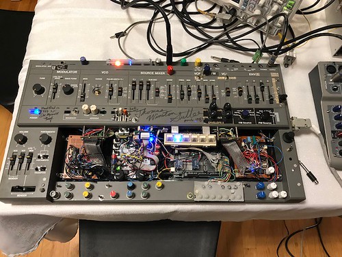
There’s a heck of a story behind THIS instrument! I categorized this DIY marathon here with the electroniums only because the result was not ‘modular’ in any sense.
IT STARTED LIFE AS AN INNOCENT 80’s MONOSYNTH
Let me start with my highly self-centered opinion of the original 1983 design of the Roland SH101.
The sound is remarkable.
If you like analog, The 101 is an analog’s analog!
How Roland got there under the hood is also remarkable… but not exactly in a good way.
The schematics are up in several places on the web (all hail the late, great, Kevin Lightner/SynthFool!) and even a cursory analysis exposes a pastiche, a please-all/please-none hodge-podge, typical of design-by-committee, the members of which seem to me as if they’d never met one another. I speculate that Roland rushed this to market and I feel bad for the lead engineer who had to kluge and patch all the disparate stages together into something coherent on the surface*.
One case in point is that while the SH101 could run on a pile of D-Cells or a 9V dc wall-wart supply, inside, this power had to be boosted, reversed, bent, folded and mutilated into no less than 7 different voltages** because almost every section was designed to run on different voltages(!) What a mess! And all of these internal DC-conversion contortions were done by a maze of circuits that included a tiny transformer. In my humble opinion the DC power conversion section is the biggest Achilles heel in the original design and I think it’s a time-bomb in every original SH101 that’s still working.
I think it can also be argued that the design left a LOT of features on the table considering what was left unused on many of the internal components.
For instance, the SH101’s heart … the VCO, is the venerable Curtis CEM3340 chip. but Roland only used the sawtooth and pulse wave outputs of this chip, leaving the triangle wave output unused. They also did not implement the CEM3340’s formidable linear FM capabilities.
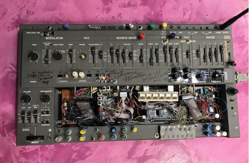
I’m apparently not the only one who thinks that Roland under-utilized the analog components because, in the 1990’s, a fellow named Philip Pilgrim sold a substantial number of ‘bag-o’-parts’-syle kits under the sobriquet of ‘Nova Mod’. These kits added an impressive number of features to the SH101 with no added active circuitry(!) This was possible because there was a ton of capability in the SH101 that could be tapped just by adding passive connections under-the-hood. I installed the NovaMod kit in the SH101 seen above in 1999.
I want to stress that all of these complaints are academic. As-Is, the SH101 is mighty fine sounding analog monosynth, and I’d never have even noticed, much less cared about the under-the-hood design compromises that Roland made …. if my SH101 had kept its shit together. And I admit that this kind of design-level second-guessing is utterly punctilious in terms of Roland’s clearly commercial objectives. But these speculations DO matter….. a lot….if you shift the context to DIY.
… and that context was definitely, involuntarily, and irreversibly shifted for me in late winter 2020.
I loaned the SH101 to a musician who had very limited exposure to analog, so that he could hear what he was missing. Just before loaning it to him I did a complete check of the features and discovered that the keyboard had 2 dead keys. The SH101 has a membrane switch keyboard and just getting access to the mechanical switch requires prying off an epoxied plastic retainer. <Ugh!> I regard keyboards with a degree of disdain anyway. So I made sure the user had a MIDI-to-CV converter, and obviated the whole issue by removing the keyboard entirely. Then I dropped it off at his house. He was enthralled with the sound, so it was ‘mission accomplished’ as far as I was concerned. But the garden harbored a serpent, and in March 2020, the SH101 pretty much just burned-up on him!
The poor guy was terrified that I’d be livid, and attempted a repair ( which did fix one problem ) but the entire internal power section had failed systemically, sending the wrong (and sometimes reversed) DC voltages downstream into all the circuits. There was just no way to band-aid a systemic failure like that.
For the record, When he worked up the courage to tell me what happened, I emphatically assured him that hardware failure in old analogs is a familiar landmark and endemic to the territory, and no one was to blame. I retrieved the remains from him and took it home.
What happened after that went light-years beyond a repair or restoration (I’m incompetent at both of those noble professions anyway)
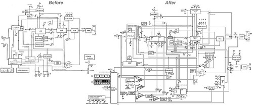
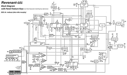
When all was said and done the cheerful little monosynth had evolved into… a … uh …. well… Just compare the before & after block diagrams below and decide how you’d put it into words.
WHAT DO YOU DO WITH A DEAD SH101?
The SH101’s original voice is a Curtis chip CEM3340 VCO (mix of saw or Pulse wave) into a Roland IR3109-based 4-pole lowpass VCF. The IR3109 is basically 4 OTA’s on a chip with a common control-line and Roland just frames it out with the caps & resistors to create the filters in series.
The IR3109 survived the power section conflagration , but the CEM3340 was not so lucky. And unfortunately, it’s demise was not decisive. It declined slowly into attrition and death.
The first priority was to remove the failed power section and build an external supply to provide all those required power rails. This is a tedious chore, and I hoped that would be the extent of the ‘repair’. But no such luck . With the new supply in place I noticed that the amplitude of the existing SH101 voice seemed to be getting a little narrower each time I monitored the output. after a couple of days the internal amplitude had dropped to less than a half a volt. I whistled valiantly through the graveyard and attributed this to the fact that I’d been handling the trim-pots on the VCA a lot with all the repair work.
Then, finally, I was getting –nada– from the output. I chalked it up to being crosseyed after a long day and went to bed.
Grimly, I opened it all up again on the next morning and repeated a painstaking signal trace backwards from the output. The VCA & VCF were fine but the venerable original Curtis CEM3340, was not squirtin’ waveforms…at all. And the 3340 was almost too hot to touch. Damn!
The essence of the sound of the SH101 is that Curtis-Chip Saw/Pulse mix through that Roland single IC23109 filter chip. And now the CEM3340 was kaput. The CEM3340 VCO is a great analog oscillator but not irreplaceable – the real drag is that it’s just a shame to lose one of those original Curtis chips.
My immediate instinct was to cut my losses and bail on the SH101. But… (but, but, BUT!) …. the VCF (IR3109) chip seemed fine. as did the rest of the circuitry. CEM3340’s are still obtainable but my ‘what-if’ fetish was starting to itch. and I happened to have a pile of the old LM566 linear VCO chips . So I built a exponential converter for the 566 VCO chip using a recipe by a fellow whom every analog DIYer in the U.S.A. should venerate as a patron saint, Thomas Henry.
In his ‘Analog VCO Chip Cookbook’ Prof. Henry offers a series of designs for exponential converters that make several golden-era instrumentation chips behave well enough to play a do-re-mi scale in response to 1/12v steps. Prof. Henry is a teacher by trade and the book is explicitly and unequivocally, a tutorial; an incremental account of Prof. Henry’s serialized experiments culminating in an ideal practical design at it’s end. This is a fact that I ignored to my detriment because chapter ONE is devoted to the 566. I neglected to remember that chapter one ends with the sentence. “in a nutshell, the 566 is perhaps not a good choice for a 1v/Oct VCO”
Yeah…
I behaved like the smug pedant that I am, and eschewed the text in favor of the just reading schematics. I rashly soldered the 566 circuit to a perf that already hosted a critical circuit for the SH101, and, compounding my arrogance, I soldered not only the VCO, but also an integrated CV waveshaper to the perf . And THEN discovered that the whole damn thing would not track more than 1 octave for love or money. Disappointing indeed … and 100% my own damn fault.
I admit to a deep bias against 1v/Oct tracking ….and I almost threw up my hands again and abandoned my notion of respecting the SH101’s equal-tempered heritage at that point… but I swallowed my pride and stayed the course for two reasons:
-the Thomas Henry 566 VCO & waveshaper combination sounded ludicrously good in terms of TIMBRE. The tracking was shit. But the tone was dead-cool! Surely, I thought, this failed experiment could be used for SOMETHING.
And…
In the same drawer with the 566’s I had some CEM3394’s that were salvaged from some 80’s wreckage. The 3394’s were Curtis Chips and I KNEW that they track very well… and they were just sitting there!
The 3394 is a third-generation CEM chip. It’s not just a VCO on a chip, it’s a complete ‘voice’ on a chip
– a VCO->VCF->VCA in a 20-pin DIP package
-Its VCO section is the same rock-solid core as the 3340 and it will generate the same 3 waveforms as a CEM3340, but not simultaneously. You select the VCO waveform with a voltage on a designated ‘select’ pin.
-It was designed to operate with +5/-5 power rails; This was optimized for the digitally-control hybrid synths of the late 80’s like the Sequential Circuits MAX. These power rails were among the ones already implemented in the SH101.
-The outputs of the 3 sections (VCO,VCF,VCA) are not brought out on pins. You can only get the audio at the output of the last-stage VCA- but with the VCF and VCA wide open (at max) the VCO wave form is passed- through in ‘pure’ form and…. all 3 waves are at the same amplitude level.
-The 3394’s on-board VCF is luxurious, it has voltage controlled Resonance (as well as Cutoff Freq.) and internal amplitude-compensated resonance so that when you drive the VCF into self-oscillation the volume stays consistent. This is HARD to implement in analog circuitry. Hats off to the late Doug Curtis!
-It has an internal FM feature that gives you voltage controlled feedback of the VCF output back into the VCO. The effect of this is a ‘lite’ form of waveshaping.
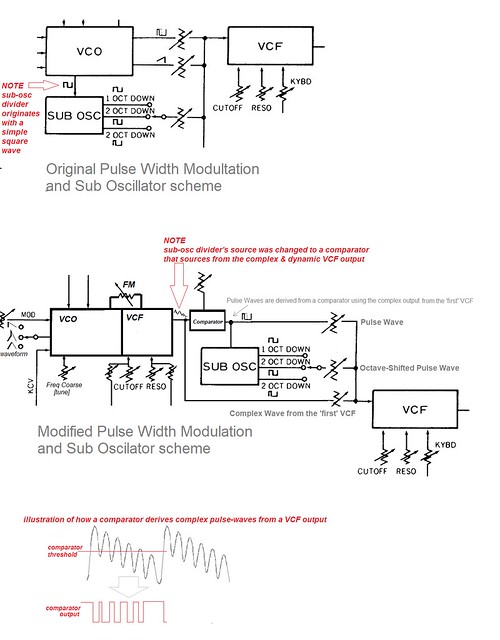
and if I applied a comparator to the output I could get a simultaneous pulse wave…… hmmmmmmm
This really excited me because with all the onboard capability of the 3394, the output wave could become very complex and consequently a pulse-wave derived from it would be commensurately complex and animated.
Having spent a couple of paragraphs disparaging Roland’s design work on the SH101 I think I should also devote some commentary to some of the delights in their design. One of which is the ‘Sub-Oscillator’. This is not actually another oscillator but rather just a pulse divider on the the pulse output of the CEM3340. Roland used a tried & true divider scheme utilizing a CMOS 4013 ‘dual-D’ type flip-flop chip. The output of which is actually not a pulse wave at half or 4-times the rate of the input pulse, but rather a kind of asymmetrical staircase wave. This quirk of the flip-flop divider gets much more interesting when the input pulse is animated and the complex output of the CEM3394 is definitely more dynamic than a simple pulse wave.
The IR3109 VCF really put me through the wringer a couple of times during the project. But, like Dick Cheney’s left ventricle, I’d just keep hitting the damn thing with the de-fib… and it’d show up for work again the next morning (!!!).
These near-death incidents led to some unexpected turns in this saga.
Namely…
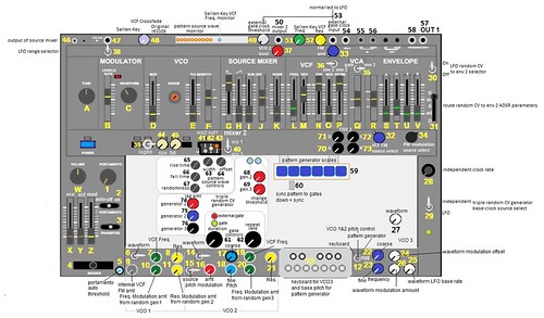
there are now 2 VCF’ stages in parallel in the in the signal path. (notice the VCF at the top around controls 51 & 52)
During one of the many episodes when the synth flatlined on the operating table, my testing indicated that the IR3109 had stopped working. I was confused & suspicious because it was not heating up like the CEM3340 did, but I was getting nothing but DC out of the signal path
So I sighed a very heavy sigh, and thought long and hard –again–about cutting my losses, and salvaging the whole project for parts. But after testing the VCA extensively to make sure it was still working, having swum halfway across the pacific, I reluctantly decided that I’d build a DIY VCF of a different type than the original (a 2-pole Sallen/Key design not unlike the Korg MS-20 VCF) So I finished that, and then when I installed it for testing in the actual SH101, I noticed a signal had appeared again on the output of the IR3109(!!!!) This story was accumulating more twists than an Agatha Christie plot.
My best guess is that I overlooked some parameter when I tested the IR3109. When things go south in a massive tangle like this, adrenaline absolutely fucks with my thinking.
But the upshot is that I now had TWO VCFs of different topographies installed rather than one. So I decided to invest in the addition of a crossfader and just roll with it…. and keep ’em both!
SO MUCH FOR THE VOICE ENGINE – HOW ‘RE YA GONNA PLAY THE DAMN THING?
With the keyboard gone, I faced an important decision. How will a muscian play this thing now? Should I go ‘full-on Doc?’ and abandon the 12-tone intervals? That would open up a host of exotic and interesting options for VCO topographies. But on the other hand I’ve already built a butt-load of electroniums that eschew the enforcement of the equal-tempered scale, and I’d never built one that embraces it deliberately. So I decided to respect the musical aesthetic of the SH101’s original keyboard-centric design and use VCO’s that COULD be scaled to 1v/Oct. This set the rest of the project on a path that was long, dark, and teeming with perils.
With CEM3394s in place, I had a scheme that would afford 1v/Oct VCO tracking capability. But for equal-tempered steps I’d need a way to generate rock-solid 1/12v steps. I had kept the SH101’s external gate & CV inputs intact, but I felt that relegating the control ONLY to external sources would have been kind of a tawdry cop-out.
But…. what scheme should generate the steps?
My experience is that analog electronics are just plain BAD at generating precisely-spaced steps . This is one reason that I always had no patience with people who complained about high-maintenance tuning on their analog keyboard synths after digital & hybrid synths were ubiquitous on the market. Digital designs are fantastic at precision, consistency, & repeatability. Apply the optimal tool to the job it does best! If you want trouble free ‘automatic’ tuning stability then just buy the damn DX7 and adapt. Analog just doesn’t roll that way.
A keyboard was out of the question, for conceptual reasons, as well as the fact that I’d already used up most of the real-estate for the perfboards I’d added. And a sequencer was likewise abhorrent to my tastes. I find the conventional sequencer concept stolid, polite, predictable, and drab. And if I designed a sequencer with enough features to be interesting to me, the external controls I’d need to deploy would occupy as much real-estate as the old keyboard did.
As a concept, I like the spontaneity of arpeggiators a little better than a sequencer, and the original microprocessor had arpeggiator capability. But it was tied to that darn diode-matrix keyboard scheme. I’d have to simulate the original 2.5 octave’s worth of keys somehow. And moreover, that old 80’s arpeggiator scheme was still a bit pedestrian and predictable for my tastes. So I decided to marry the alluring turbulence of analog with the precision of digital to generate stepped CV patterns. and for precise 1/12v stepped CVs, I turned without hesitation to the method that does CV precision best. Doc is going digital. And… yes… Digital meant I’d need a quantizer
yes … you read that right … a quantizer…Et Tu Doc???? Oh the hypocrisy! (sigh)
In light of my habitual diatribes about reflexive use of quantization, that’s a fair cop…and of course, there’s a story there-
This design decision was made after I’d realized the CEM3340 was a goner.And the on-board 80’s era microprocessor that Roland used for a sequencer & arpeggiator was still working…..(IS still working ….. it’s still dutifully functioning as a sample hold for the original random step generator) but it required a now-amputated diode-matrix keyboard for input.
So I deliberated & considered, and the scheme I chose is this:
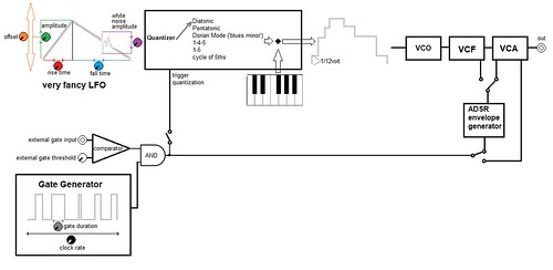
An analog triangle-ish LFO with controls over Rise time, Fall time, Offset, Amplitude, and Random Deviation Amount, is fed into an Arduino based digital quantizer. The quantizer will impose one of a selection of 6 ‘grids’ that will output 1/12volt steps of a Diatonic, Pentatonic, Minor Blues (b3, b7), Cycle of 5ths, 1-4-5, or 1-5, scale. At maximum amplitude the patterns will span 3 octaves, (3v) at the periodic rate set by the sum of the rise & fall time controls. The quantization occurs either at the free-running rate of the Arduino’s processor, or it can be triggered by the gate generator, which is an analog clock with an external sync input. I scavenged one octave’s-worth of buttons in a Faber layout from a tiny Casio VL-tone and I added those ‘keys’ to the quantize algorithm as ‘starting note’ offsets. I also created a 1-octave DAC output for the ‘keyboard’ outputs alone.
The ‘active ingredient’ here is that the clocked gate generator is independent of the 3v triangle(ish) LFO. That means the cycles of the ‘rhythm’/gates will never be in lock-step with changes in pitch. In a commercial design this would be suicide. But for making interesting evolving patterns, It’s just what the doctor ordered. I did concede to adding a ‘sync’ feature that triggers the quantize ‘snapshot’ on the trailing edge of the gate but the rise/fall cycle of the overall ‘melody’ contours will still never sync to the gates cycles. The melodic repetitions will never exactly lock-up to the rhythmic repetition patterns.
In the design phase I had high hopes for this scheme and frankly I’m very accustomed to being a bit disappointed when the concept becomes a reality. My concepts usually fall short of my initial design goals. But this design was a rare exception. It exceeded my expectations. I’m REALLY pleased with how it ended up sounding in terms of varying permutations of pitch & rhythmic patterns. The 3-octave patterns were interesting and dynamic and the CEM3394’s tracked 1v/Oct …pretty much…. well enough to keep up with the precision of the Arduino’s stepped output.
And ….remember that 566 VCO debacle that barely tracked 1 octave?
I decided to squirt the little 1 octave ‘keyboard’ steps that I was using for the pattern starting-note into a DAC of their own and feed that to the 566-based VCO.
The VCO tracks OK(ish) over that one octave, and so I decided to deploy it as a kind of drone or pedal-tone pitch for parallel polyphony with the ‘main’ cycling 3-oct pitch patterns. With the dynamic waveshaping it can render a killer bass pedal-tone. I also decided that i’d add a second, parallel output with it’s own mixer for this polyphonic mix. (This section can be seen in the lower right of the block-diagram around ‘VCO3’, and the mixer/VCA near controls 40-43)
To be frank, that scheme turned out kinda dodgy in my opinion, mostly because the 566 VCO does not track even its one measly octave well at the low & high extremes of its full range, and it requires a lot more tweaking to chase the resonances than I had hoped for. But it worked well enough to earn it’s real-estate in the final implementation.
In the end, the whole project occupied 5 months at an average of 20 hours per week and after such a long concentrated time I desperately needed to get a third-party perspective. So I put the Revenant-101 in the hands of my friend and band-boss, Tory Z Starbuck. He immediately focused on that added output channel with VCO3. So I’m not definitely not writing it off. Other players almost always teach me a substantial wealth of knowledge about my designs.
* This speculation about how the SH101 was designed was confirmed later in this saga by a member of one of the 1983 design teams who is retired now and (for obvious reasons) would prefer to remain anonymous. Nevertheless making the acquaintance of this generous and erudite gentleman was one of the joys of this ordeal
** -5v, 0v, +4.5v, +5v, +9v, +14.5v, +15v
Comments are closed.