The QDVCO (quick & dirty VCO)
The purpose of this article is mainly educational at an elementary level. It is defintely not trying to proffer a VCO circuit with which you can impress your friends by playing the synth solo in ‘Lucky Man’. Still… the schematic in fig.5 is a tested, practical circuit that I use extensively in my cacophony-prone electroniums.
One way to make an oscillator is to combine two very basic electronic circuits. One is called a comparator. The other is called an integrator.
Their functions are very simple.
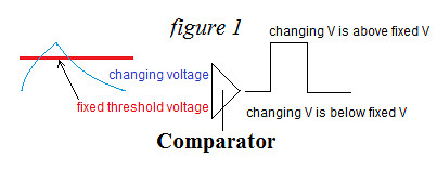
The COMPARATOR compares two voltages and switches its output all the way ‘ON’ when one input is higher than the other, and ‘OFF’ when it is lower.(see fig. 1)
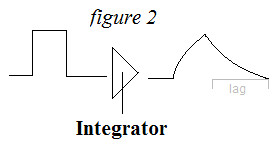
The INTEGRATOR slows down the movement of voltages, sort of like trying to run fast, in waist-deep mud. Integration functions cause transitions to ‘stretch-out’ and take more time to complete. (see fig. 2)
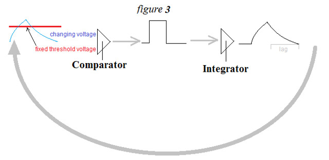
if you connect these two devices in a circle (or feedback-loop)(see fig 3) every time the comparator switches off, or on, the integrator slows down the transition and sends the slowed-down voltage-transition BACK to the comparator’s input. This triggers another switch and the whole cycle begins again, and again, etc. This will continue until you cut power to the circuit.
This is the concept of a simple comparator/integrator oscillator.
feedback loop
A simple Oscillator will cycle (more or less) steadily at one frequency (pitch). This is fine for doorbells but, for music, one needs to be able to vary pitch. In this example, variation of pitch is done by changing the degree to which the INTEGRATOR can slow down the transitions. (varying the ‘lag time’)
Fig. 4 illustrates such a simple oscillator with actual circuitry. The Value of ‘RT’ is up to you. Start with 10k and then vary it to observe the effect.
figure 4
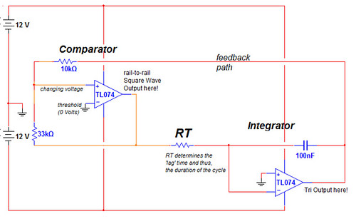
When we implement this circuit with actual components the easiest way to vary the INTEGRATOR’s characteristics is to vary the resistance between the incoming switching voltage from the comparator and the input to the integrator. (RT) This can be done with any electronic component that allows a player to vary resistance. But in the realm of analog synthesizers, the method of choice for varying the functions of a circuit is by varying the resistance with an external voltage, known as a CONTROL voltage.
Transistors can be used for many things but in the figure-5 circuit i use it as a very crude voltage-controlled resistor that changes it’s resistance in response to a voltage at it’s base.
Now we get to the specifics of a Voltage Controlled Oscillator (VCO) circuit.
Fig. 5 illustrates the basic circuit including the component values with which I often implement it. ‘RT’ is replaced with a PNP transistor (which makes this version very quirky by conventional standards) The leftmost op-amp is an inverting DC voltage amplifier/mixer that varies the resistance across the emitter & collector of the transistor. You can add other control voltages through resistors at the summing-node.
figure 5
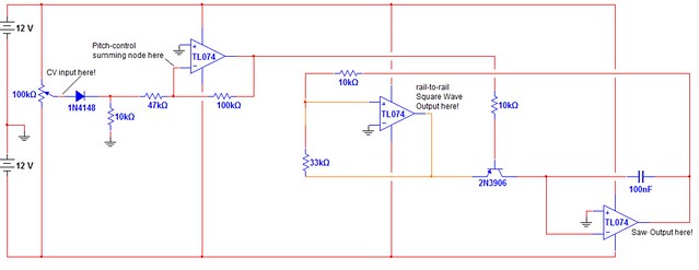
I stress that this is a very quirky, ‘quick & dirty’ VCO. It does not respond uniformly to voltage changes and thus, it is not at all well-suited to playing scales that are easily tuned to a piano*.
I have used the QDVCO circuit as a ‘basic recipe’ for years. I have used several schemes to vary the pitch control resistance (‘RT’): simple potentiometers, photoresistors, Vactrols, and transistors. The pros & cons of using a transistor for varying RT break down thusly:
Pros:
Cheap
Easy to obtain
Straightforward to implement
uses very little physical space
Cons:
Very quirky and uneven transfer of voltage to resistance
Some of the control voltage (actually current) always leaks into the output
It it almost always requires a third op-amp to condition the control voltage to suit your application.
The capacitor in the integrator sets the range of the QDVCO. Use a higher value (ie 10uf) to slow it down to lower frequencies or a lower value (ie 10nf) for higher frequencies.
If built with the component values as shown you should expect performance to approximate this table:
Control voltage = output frequency
-12-0v = 0hz
0.2v = 25hz
0.3v = 250 hz
1.1v = 2.5 khz
5-12v = 10 khz
The square wave output amplitude is 24V (-12V – +12V).
The sawtooth output amplitude is roughly 5V (-0.7v – +4.3v)
I recommend using TL074 opamps but I suspect that any fairly modern fet-input op-amp would still work. I have also used the LM324 successfully.
*That requires extensive precision circuitry that is WAY beyond the scope of this article.
Comments are closed.