form-factor schmorm-factor!
I get notoriously cranky when lots of smart creative folks convene on an internet forum to discuss the marvels of the analog renaissance, and then produce barely anything but pages of anxious hand-wringing discourse about the PANELS & PATCH-CORDS on those analog synthesizer modules.
Bah! Humbug!
Am I unsympathetic to the fact that many of these folks are musicians, and not metalcraft/electronics technicians and fear potential damage to their significantly expensive gadgets? No…
I AM sympathetic because in the past, I have walked many miles in their moccasins and shared their anxieties. So I was astonished when I learned how little knowledge was required to understand that the differences among ‘form-factors’ are, in large part, trivial and arbitrary, and how easy it was to integrate any module with any form factor into any system.
Let’s begin with the cables and connectors:
Can I connect 1/8″ modules to 1/4″ modules, and can I connect them both to banana plug modules?
YES!
(Background: In this article three terms will be used interchangeably in this article. ‘Ground’ = ‘0Volts’ = ‘Shield’. For the purposes of this topic it is safe to assume that all three terms are synonymous.)
(Disclaimer: you know the drill – no guarantees of any kind are implied, DIY is always at your own risk)
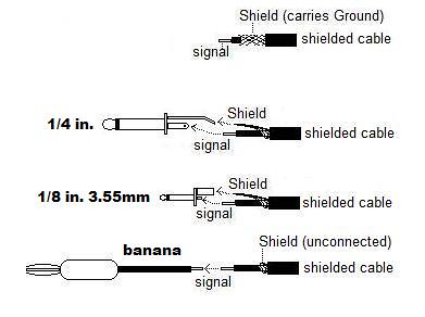
At the time of this writing 2-conductor patch cords are the most common1/8″ (3.55mm) and 1/4″ connectors are both 2-CONDUCTOR types. The center conductor (tip) carries the SIGNAL . The other conductor (sleeve) carries GROUND.
The Ground conductor does two jobs:
-TRANSMISSION: it connects the ground from the power supply of the device at one end of the cable to the ground of the power supply at the other end of the cable.
-it SHIELDS the signal from interference that may be in the environment around the cable. At the level of signal on most analog synths, this shielding function is very handy but rarely vitally necessary because the signal is many hundreds of times stronger than any airwave-borne interference.
If the cable is connecting two jacks that SHARE a power supply (ie 2 jacks on the same device) then the ground connection serves no transmission purpose; and its shielding function is arguably rather superfluous.
You can chop a 1/8″ end off one side of a cable and solder-on a 1/4″ and it will work perfectly. Thus 1/8″ & 1/4″ systems are completely compatible in every way except physical size.
Enter the BANANA plug!
Banana cables are ONE conductor, SIGNAL-only cables. They dispense with the Ground/Shield conductor and connect only the SIGNAL conductor. Per the above, AS LONG AS YOU ARE CONNECTING JACKS THAT SHARE A POWER SUPPLY. This signal-only scheme works exactly the same as the shielded (1/8-1/4)scheme, because only the connection of the signal conductor is actively doing anything. The problem arises when you connect a signal-only cable between jacks that are on two different devices that have ELECTRICALLY SEPARATE power supplies, and thus electrically separate grounds.
So, what are we losing when we lose the Ground? A signal is a RELATIONSHIP. It can only do it’s job if it knows where it’s ‘Ground’ is. Ground is a REFERENCE. 1 Volt is only 1 Volt if the machine knows where 0 Volts is. 9 Volts is only 9 Volts if the machine can tell that it’s 9 times higher than 1 Volt was from that previously mentioned 0 Volts. With a two-conductor (1/8,1/4) cable, the cable carries it’s own 0-volt reference to each end. When you connect (ie) a 1/8″ cable from a Blacet VCO to an Arp 2600 you are , in addition to connecting the signals, connecting the 0-Volt Ground of the Blacet power supply to the 0-volt Ground of the Arp power supply. As soon as that jack is plugged-in, the two power supplies instantly ‘Agree’ on where 0-Volts is.
Now here’s where it gets subtle…If you plug another 1/8″ cable in between the Blacet and the Arp, you import another signal but you also REPEAT the Ground/0-Volt connection of the power supplies. This is VERY redundant and inefficient from a pure engineering standpoint. Only ONE conductor need connect the Ground/0V of one power supply to another. Once that connection is made, both power supplies are using the same reference and then you only need ONE conductor to carry signals back and forth.So… if you connect ONE wire among the Ground connections of ALL the power supplies in your rig (and thus, ALL of your power supplies agree on where 0 Volts is) then you can use a cable with (ie) an 1/8″ two-conductor plug on one end and a single-conductor banana on the other. You can just leave the shield unconnected (and insulated) on the banana end. This hybrid connection can be accomplished with special patch bays and mults too. But such simple (mostly empty) passive devices are not NECESSARY for the translation.Most commercial purveyors of single-conductor, banana-patched, analog systems will provide a patch-point that provides external access to ground. They just don’t always advertise or document it. In sum, there is no reason why commercial 1/4, 1/8, and banana systems can’t be interconnected easily and with no risk of damage.
The secret is to connect the grounds of ALL your power supplies together.
If the notion of stripping wire and soldering strikes terror into your heart. There are commercial solutions especially if all you need to do is connect 1/8 to 1/4. In the USA, Radio Shack* still sells adapter cables with a 1/4 on one end and a 1/8 on the other . (42-2433 ). They also sell adapter-plugs that will turn a 1/8 into a 1/4 or vice versa (274-325 , 274-366). Use ‘mono’ adapters. The stereo versions will -usually- work just as well but mono is certain to work in all cases. If you do shop for commercial adapters don’t waste your breath asking the supplier for assurances that your scheme will work, or will be risk-free to your gear. None of them will risk any liability.
2-conductor, 1/8 or 1/4 to banana adapters are harder to find commercially but any technician with rudimentary skills could fabricate them.
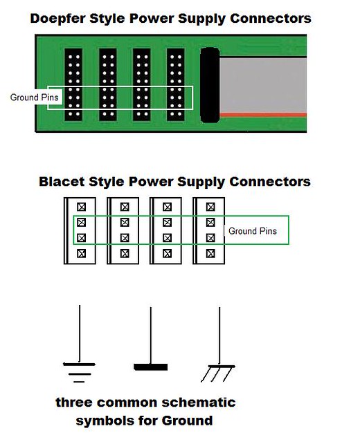
Below is an illustration of some common analog synthesizer DC power distribution systems and the location of Ground plus common symbols for Ground if you are comfortable reading schematics. This is a starting place for those with the aplomb to tap into the power supply ground in pursuit of a homemade common grounding system:
Now that we’re talking about power supplies. Let’s venture on to some of the thinner ice; 12 volt vs 15 volt power supplies…
(disclaimer: read the last sentence about THINNER ice… no guarantees!)
First let’s address the audio and control-voltage patchpoints on the FRONT of the module.
The ice is thinner here because safe interconnection is dependent on the manufacturer voluntarily not violating a couple of widely accepted conventions, namely:
1) no patch point will ever output a voltage higher than 10V nor lower than -10V
2) outputs and/or inputs will be protected with current-limiting resistors.
Don’t worry if you don’t quite understand number 2, it’s an engineering principle that simply means that the designer installed a component that will try to keep any accidentally excessive or out of range electricity (especially quick pulses) from frying the circuitry behind the panel.
I know of no commercial manufacturers of analog synth modules who DON’T adhere to these two conventions.
…and what those two conventions mean in practical terms is that, once you get a cable with the proper connectors fixed-up, ANY type of synth modules can be patched to any other type without danger to the innards! The results may not work as you expect but you will not hurt the module!
NOW WE ARE AT THE THRESHOLD OF THE DARKEST PART OF THE JUNGLE:
THE POWER CONNECTIONS ON THE BACK! (cue ominous music)
So... What about those power-supply connections in the back? Can I rig up something that will allow me to power (for instance) my 15-volt module from a 12-volt power supply?
The answer is one of those huge ‘It depends’!
Please know that this topic is deeply into the province of disclaimers and if you cannot abide risk, then you should close this page now and settle for the expanded patching options above.
I’m going to change styles to a ‘bullet-list’ of principles at this point because there are so many contingencies and dependencies inherent in messing with power supplies that trying to thread my advice into a narrative suitable to every situation is impossible.
- -First, Contact your module manufacturer and ask them if they will advise you about what you want to do.
- -Be scrupulously and unflaggingly polite
- -Do ALL of your homework, know EVERYTHING on this list accurately & specifically:
- -the voltage of the positive output of the power-supply you intend to use (volts)
- -the maximum positive current sourcing capability of the power-supply you intend to use (in milliamps or amps)
- -the voltage of the negative output of the power-supply you intend to use (volts)
- -the maximum negative current sourcing capability of the power-supply you intend to use (in milliamps or amps)
- -the number of other modules that will share this same power supply and how much current, at maximum, (in milliamps) each module consumes.
Don’t even bother to call a designer if you don’t know these details, and even if you do all of the above , it is probable that the designer will advise you against your plan. There are dozens of EXCELLENT reasons for this. But a few designers may be willing to advise you as long as you assure them that you are assuming ALL the risk for your foolhardiness.
I have powered modules from homemade supplies, and at voltages other than those for which they were designed. With the clear caveat that you can easily fry a module with any mistake. Here are the rules-of-thumb I have accumulated:
- –less voltage is almost never harmful, ie running a 15-volt module from a 12-volt supply is very unlikely to fry it. It may very well act funny, or not work at all, but it is unlikely to emit smoke and die.
- –more voltage is almost always harmful. ie running a 12-volt module from a 15-volt supply is very likely to emit smoke and die. The ONLY way this can work is if the designer approves it, or you have the schematic and the knowledge to read and understand it at a level from which you can determine that there is no risk to the circuit.
- -once the above two hurdles are passed, the issue of connectors remains. There is no magic to types of power-supply connectors. The most critical consideration is that you must make absolutely sure that you connect: positive to positive, negative to negative . and ground to ground. The next most critical consideration is that you should use wire of a gauge that is thick enough to carry the current easily. As a rule of thumb, thicker is better.
- -Some fancy modules (especially digital-analog hybrids) require a positive 5V supply in addition to the other three supplies (positive, negative, ground) If so, you must make sure that your new supply can supply the additional required +5V. It is never advisable to try to monkey with the voltage on the 5V supply.
PS:
Did you find inaccuracies in this article?
Good for you!
Here’s a parable:
I have read many times in a well known Electronic Music Magazine that one should NEVER disconnect the ground (third) pin from an AC power cord even if it does break a ground loop and stop an audible AC hum in a critical audio path. The magazine is exactly correct in taking this position. Breaking the earth-ground path creates a serious potential safety hazard. This is good and responsible advice.
I once attended a roadshow that was sponsored by this magazine. There was to be a jam at this event. The band consisted of then-current members of the magazine’s editorial staff. I was contracting with the venue in which the show took place. A portable stage had been set up in the middle of a large exhibition hall and the power to the stage was directed through a 75-foot industrial extension cord. During soundcheck the house signal was beset by a nasty line hum and all attempts to stop it by the professional soundtechs on the crew failed. A half hour before the show I was talking to one of the band-member/editors about the line hum. It bears mentioning that this particular editor was one of the authors whom I know had stressed the proscription against ‘lifting’ the ground on AC power in several of his articles. He grabbed his setup toolbox followed the AC extension cord to its wall plug and, without warning his colleagues that he was cutting stage power, he pulled the plug, put a 3-to-2 pin adapter on it and plugged it back in. Of course the line hum dropped to a nearly inaudible level, the soundcrew experienced a few seconds of panic at the unexplained ‘power outage’ but everybody seemed relieved that the mysterious event had killed the hum.
The moral of this story is that there is no such thing as uncompromised quality. The universe (and yes this DOES include the laws of physics, Scotty!) has a thousand tricks up its sleeve and it changes the rules a little bit every nanosecond. A quiet channel today can be noisy one tomorrow even when YOU didn’t change anything and real-deal audio engineers are all world-class at ADAPTING.
Specifically…
It is true that there are differences in quality between shielded and unshielded signals and it is also true that the audibility of these difference can be significant under some conditions, in some environments.
No scheme is perfectly quiet …. and ….while it may be absolutely indisputably true that it is NOT raining between the drops. Somehow we all get wet in the rain.
The principles here are practical not pedantic.
*as of this writing (in 2013) This is sort of miraculous considering how aggressively Radio Shack is striving to get out of the market for supplying component parts that are useful to DIY practioners!
Comments are closed.